


Next: Intra-node Distribution Architecture
Up: Synchronisation Network Architecture
Previous: Synchronisation Network Architecture
A much simplified diagram of the network architecture proposed for the inter-node distribution of synchronisation is shown in fig 2.1. The arrows represent the logical path of the synchronisation signal.
Figure:
Synchronisation network architecture for inter-node distribution after [2]
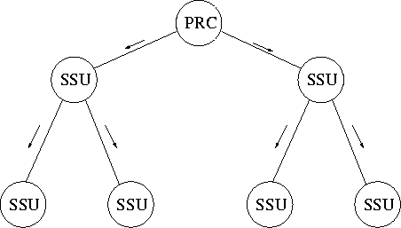 |
It can be seen that the inter-node distribution network has a tree-like topology. The figure also serves to illustrate the hierarchical relationship between clocks in a SDH synchronisation network. To avoid timing loops, it is important that clocks only accept inputs from clocks of the same or higher hierarchical level, even under fault conditions. One way this is achieved is by specifying a pull in range for each clock so that it will not stay in locked mode if presented with a signal from a clock lower in the hierarchy. The pull in range is defined [1] to be the largest offset between the frequency of the reference signal and a specified nominal signal within which locked mode is achieved.
Mark J Ivens
11/13/1997