

Next: Summary
Up: Relationship between ETSI and
Previous: Applying the ETSI Model
The material presented so far in this chapter perhaps calls into question the validity of the model used to simulate a maximum reference chain. Certainly neglecting the PLL noise filtering characteristic would seem to be an unrealistic assumption. The modelling of such a property is not contained within the ETSI model and earlier proposals [26] incorporating the PLL filtering process were criticised at ETSI standards meetings as being too implementation specific. Such filtering acts so as to reduce the overall noise and so the ETSI model can be used to obtain an upper bound on the noise in a synchronisation reference chain by simply adding the noise of consecutive clock model outputs![[*]](/~mivens/icons.gif/foot_motif.gif) noise and it was this approach that was originally adopted. It will be seen that such a simple model of a synchronisation reference chain violates the wander masks. Importantly, as will be seen in figure 8.10 for example, the noise at the end of the reference chain exceeded the mask at small observation intervals. From the PLL transfer function (3.13) which is reproduced later in this section, it can be seen that PLL's essentially low pass filter the incoming noise. Since low pass filters suppress high frequencies, and high frequencies correspond to small observation intervals, including such an effect in the model would act to lower the noise for
noise and it was this approach that was originally adopted. It will be seen that such a simple model of a synchronisation reference chain violates the wander masks. Importantly, as will be seen in figure 8.10 for example, the noise at the end of the reference chain exceeded the mask at small observation intervals. From the PLL transfer function (3.13) which is reproduced later in this section, it can be seen that PLL's essentially low pass filter the incoming noise. Since low pass filters suppress high frequencies, and high frequencies correspond to small observation intervals, including such an effect in the model would act to lower the noise for  small.
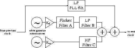
The ETSI clock noise model was therefore extended to include the filtering of noise on the input of a phaselock loop. A relatively simple modification was adopted. The phaselock loop transfer function, namely (3.13)

can be approximated to a 1st order Butterworth low pass filter for F(s)=1, with the passband edge at the PLL bandwidth (3mHz for SSU's, 1Hz for SEC's). An input was added to the SEC and SSU models with the noise from the previous clock passing through such a low pass filter before being added to the noise generated by the components of the clock. The extended model is shown in figure 5.4.
Figure 5.4:
Modification to ETSI model
 |
The additional filter has the transfer function

taking the same notation as before.


Next: Summary
Up: Relationship between ETSI and
Previous: Applying the ETSI Model
Mark J Ivens
11/13/1997


